Connect your Wattwatchers device
Disclaimer: You must ensure you have all the necessary equipment to complete this process. You should have received the following to begin the installation process:
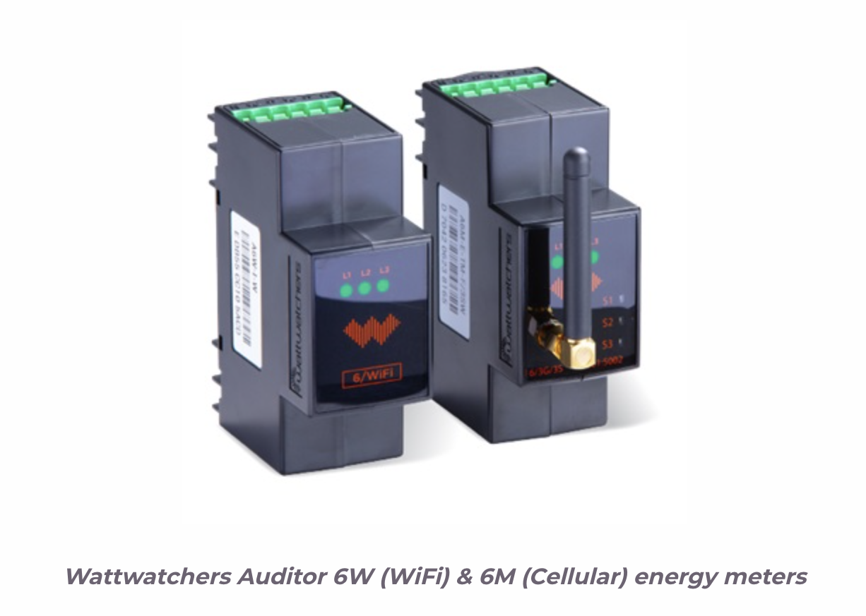
(1) Monitoring device(s) (Wattwatchers ‘Auditor’ energy meter),
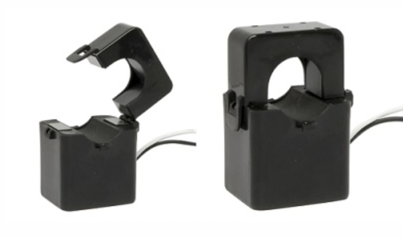
(2) Current Transformers (CTs)
(3) Wiring Tails
(4) Connectors
For commissioning, you'll need a smartphone or other internet-connected device. (Commissioning is a set of tests and inspections performed on-site to ensure that the metering systems are accurately capturing power flows at the designated metering point.)
A clamp meter can be used to double-check that the meter reading matches what the clamp meter indicates when configuring the Auditor (energy meter) and capturing installation data.
On the DIN rail, you'll need roughly 35mm of space. Additional DIN rails may be put in the meter cabinet if space is limited, otherwise, an external enclosure may be required. Make sure there's enough room to clamp the current transformers and that they're wide enough to support the cable size, which means the cable diameter should fit within the CT opening's width.
Ascertain that the voltage inputs of the Auditor (energy meter) can be isolated. The meter must be powered by an existing or new circuit breaker (depending on the regulations in your jurisdiction). You can also use a wall socket to power the meter if you're using it for single-phase monitoring. The package does not include a breaker.
Connect your device
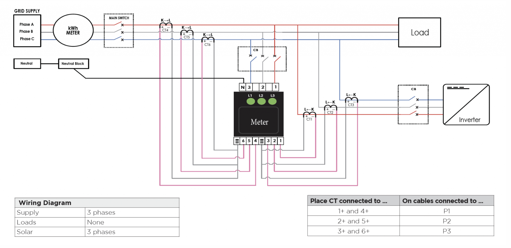
The following setups are for multi-phase or single-phase powered companies or households. P1, P2, P3, and N are the voltage connectors.
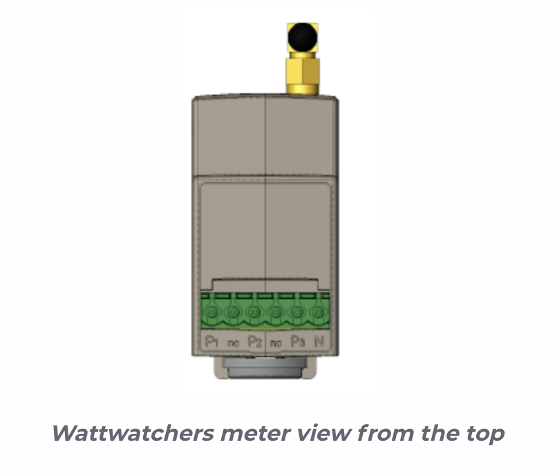
Three-phase voltage connections -> Connect voltage phases to P1, P2, and P3 using the three-phase wiring tails included with your meter. Connect N to neutral.
Single-phase voltage connections -> Connect P1, P2, and P3 to the same phase using the three-phase wiring tails that came with your meter. Connect N to neutral.
Connections to current transformers
- The arrow at the bottom of the CT should point away from the grid for grid monitoring.
- The arrow at the bottom of the CT should point away from the inverter for solar monitoring.
- The arrow should point toward the load when monitoring it.
Different-sized CTs can be utilized in groups of three on the same device, for example, channels 1-3, 60 amps; channels 4-6, 400 amps.
The Wattwatchers meter, for example, can monitor two three-phase loads with six connected CTs. The CT connections are labeled as follows:,6+,5+,4+,,3+,2+,1+,6+,5+,4+,3+,2+,1
The white wires connect to the terminals designated "" – each terminal has three wires. The pink wires are connected to the + terminals. As seen below, the CTs and Voltage phases should match:
|
Place CTs connected too |
On cables connected too |
|
1+ and 4+ |
P1 |
|
2+ and 5+ |
P2 |
|
3+ and 6+ |
P3 |
Commission your meter to SmartAnalytics with the onboarding tool
Wattwatchers' online onboarding tool (https://onboarding.wattwatchers.com.au/) uses your phone to capture installation information for each site, including device serial numbers, circuit names, and CT size.
To acquire your credentials for the online onboarding tool, contact SmartAnalytics. Log in to the onboarding tool and follow the instructions to set up your device(s) for the installation site.
Examine the meter's status indicators
All three green lights on the front of the meter should be lighted green after the installation is complete. Follow the below diagram if there is any confusion.
Contact Wattwattchers directly at [email protected] for further information on how to install your Wattwatchers gadget.
Connect your Wattwatchers gadget
The Wattwatchers meter channels must then be registered in the SmartAnalytics dashboard. This operation allows you to send data straight from your Wattwatchers device(s) to the SmartAnalytics energy analytics platform. It's really only a question of following a few straightforward steps, which are detailed in the next section.
Step 1: Log in.
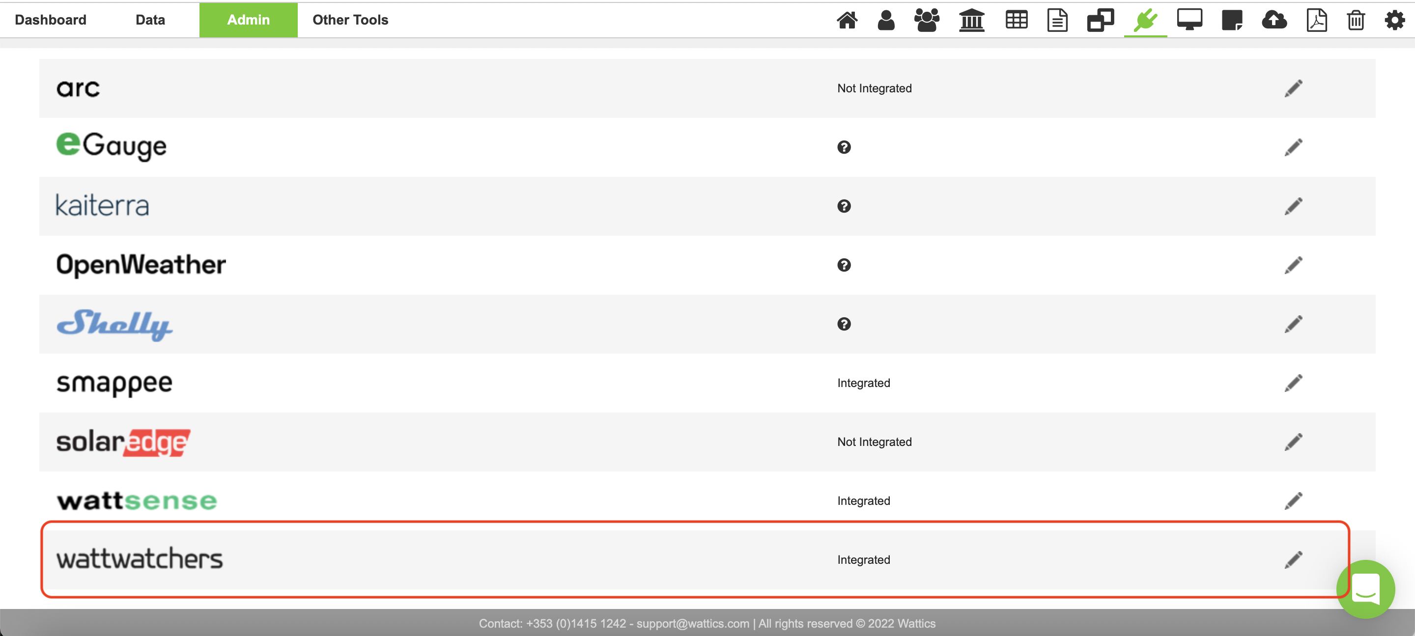
Step 2: From the admin tab, go to the integrations page.

Step 3: Open the Watt-watchers integration settings page.
Step 4: Click on New Wattwatchers API key.
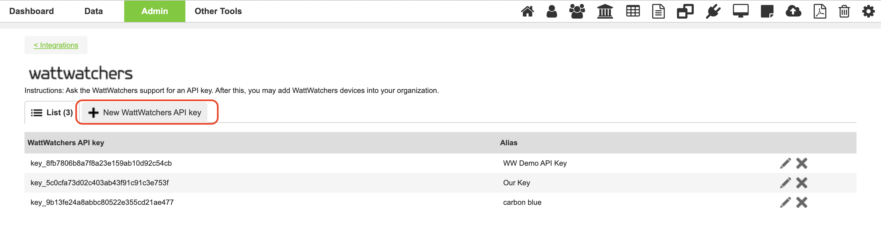
Step 5: Enter your Wattwatchers API key (1) and provide a name for it (2). Then save (3).
Note: If you don't already have an API Key, contact Wattwatchers Technical Support to get one.
Add your Wattwatchers gadget to the dashboard in step 6.
You may now add your Wattwatchers gadget to your SmartAnalytics dashboard after registering your API key.
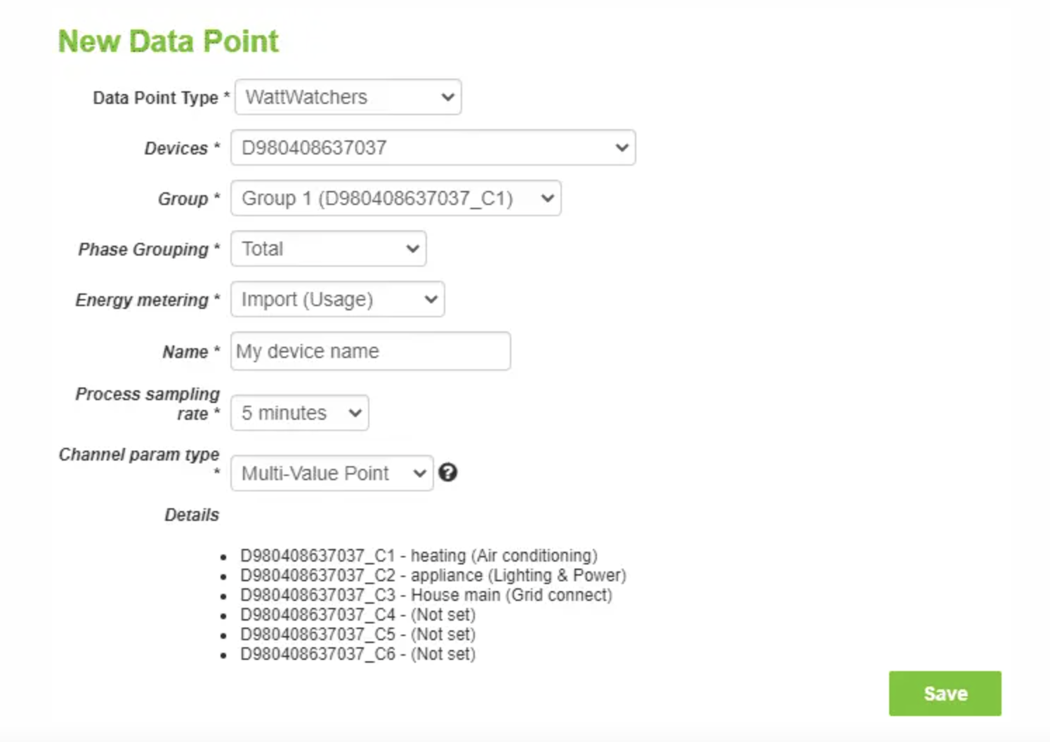
The technique for adding a Wattwatchers data point to your dashboard is the same as for all the other metered points. If you need a refresher on how to do it, go here. Please read the following instructions carefully after you've opened the data point creation webpage:
- Wattwatchers must be chosen from the Data Point Type drop-down menu.
- The Devices drop-down list displays all of the devices to which you have access using your SmartAnalytics account's Wattwatchers API Keys.
- All of the groups that were pre-configured on the device you selected when it was installed are listed in the Group drop-down list. Please see the Details section at the bottom of the page for further information on the circuits that each current transformer (CT) is monitoring.
- You can import group totals or individual phase measurements using the Phase Grouping drop-down menu. This is determined by the device's install type (single/two/three/mixed phase). Choose the one that best fits your project's requirements.
- By default, the Process sampling rate is set to 5 minutes. Feel free to change the value to something else.
- As soon as the new data point is formed, data is loaded. It is active after the available historical data has been retrieved.
- Make sure the website address is correct. It'll be utilized to figure out what time it is where your device is installed.
- Active Energy (kWh), Active Power (kW), Apparent Power (kVA), and Reactive Power (kVAr) data are available through the current Wattwatchers + SmartAnalytics integration.